1927. Haley, J. June 3.
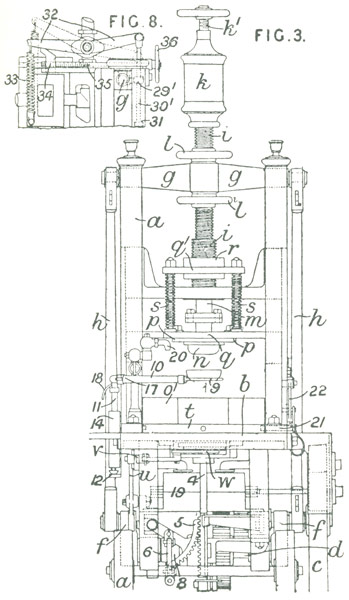
Pressing; moulding. — In a steam or other press for pressing glass into moulds to form basins, tumblers, and other articles, a yoke g, Fig. 3, connected by rods h and cranks f with a shaft d driven through spur gearing by a steam engine c, slides vertically between pillars a and carries a hollow screwed plunger spindle i passing through the screwed bosses of hand-wheels l by means of which the stroke of the plunger can be regulated. Through the spindle passes a rod m carrying the stamp or plunger n beneath which is placed a mould on a bed-plate b. The plunger passes through a ring p which overlaps the edges of the mould according to the thickness of glass required and is forced downwards by adjustable springs s fitted between a plate q1 connected to a nut r on the spindle i and a plate q fitting loosely upon the plunger. To give elasticity to the rod m and allow the plunger to remain long enough in the mould for the glass to set, a spring k, the pressure of which is regulated by a screw kl, is carried by the spindle i. The bed-plate b may be made elastic instead of the plunger. To render the action continuous, four moulds o1 are placed on a plate t, which is rotated a quarter of a revolution, at each stroke of the crank, by means of a lever w connected by a slide v and lever u to one of the cranks f and carrying a spring pawl engaging with a ratchet-wheel connected by spur-wheels with the plate t. The articles are removed from the moulds by a spindle 4 which, passing through a hole in the plate t, lifts a loose valve or plug in the bottom of the mould and raises the article on to a carrier fork 9 attached to an arm 10. The spindle 4 is actuated by a cam 8 on the shaft d engaging with a lever connected, by a link 6 and toothed segment 5, with a rack on the spindle 4. The arm 10 is attached to a rod 11 which is raised and lowered by a lever 12 actuated by a pin on one of the rods h and slides through a tube 14 having a spiral slot in which a pin in the rod works, so that the fork 9, as it moves up and down, is also turned through an arc so as to receive the article and deposit it upon a table. The arm 10 can turn on its own axis and has a finger 17 which, as the rod descends, comes against a finger 18 and tilts the fork over so as to facilitate the discharge of the article. The plate t is held in position, during each pressing operation, by a spring bolt 21, which is projected into and withdrawn from a hole in the plate by a wedge on a lever 22 actuated by a pin on one of the rods h, the wedge being withdrawn by a spring. The shaft d may be thrown out of gear with the engine by means of a treadle, and loose slips or slides are provided which may be set forwards from time to time by set-screws. The moulds and glass are cooled between each operation by a fan or fans contained in a box 19 and driven by friction - wheels from the main shaft. The box is provided with pipes 20, one conveying cold air to the pressed glass in the mould o1 and the other blowing cold air on to the plunger. An air pump operated by the press may be used instead of the fan or fans. The lower portion of the plunger is cooled by water admitted through pipes, and the valve of each mould is cooled by a jet of water admitted from below through a pipe and escaping by a pipe surrounding the inlet pipe. To increase the pressure of steam admitted to the cylinder when the glass is pressed by the plunger, a bracket 291, Fig. 8, through which passes a screwed rod 301 attached to the steam-valve lever 32 and carrying an adjustable nut 31 is fixed to the yoke g. To admit steam to work the press, the lever 32 rests on a stop 34 attached to a screwed rod 35 provided with a hand-wheel 36. When the bracket 291 descends, it comes in contact with the nut 31, thereby pulling down the rod 301 and admitting more steam to the cylinder. As the yoke ascends the valve is closed to its original position by a spring 33. The amount of extra steam admitted is regulated by a stop 34. The invention is partially applicable to hand presses for pressing glass.
|